ECTF 2025 Writeup
Table of Contents
Introduction⌗
Ayy, so this weekend, I joined team Fr334aks-mini (although I showed up fashionably late) and managed to snag the flag for the hardware challenge from ECTF 2025. Most of the challenges were taken care of by my teammates, including some of the cryptography puzzle solved by Cybermunene —honestly, I just showed up for the victory lap--being late wasn’t part of the plan. But ayy, no harm in letting the real MVPs do the heavy lifting, right? Enough talk, though—let’s get to action!
Orbit (Hardware)⌗
We begin with the challenge info:
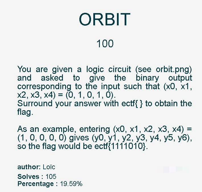
orbit.png had the following details:
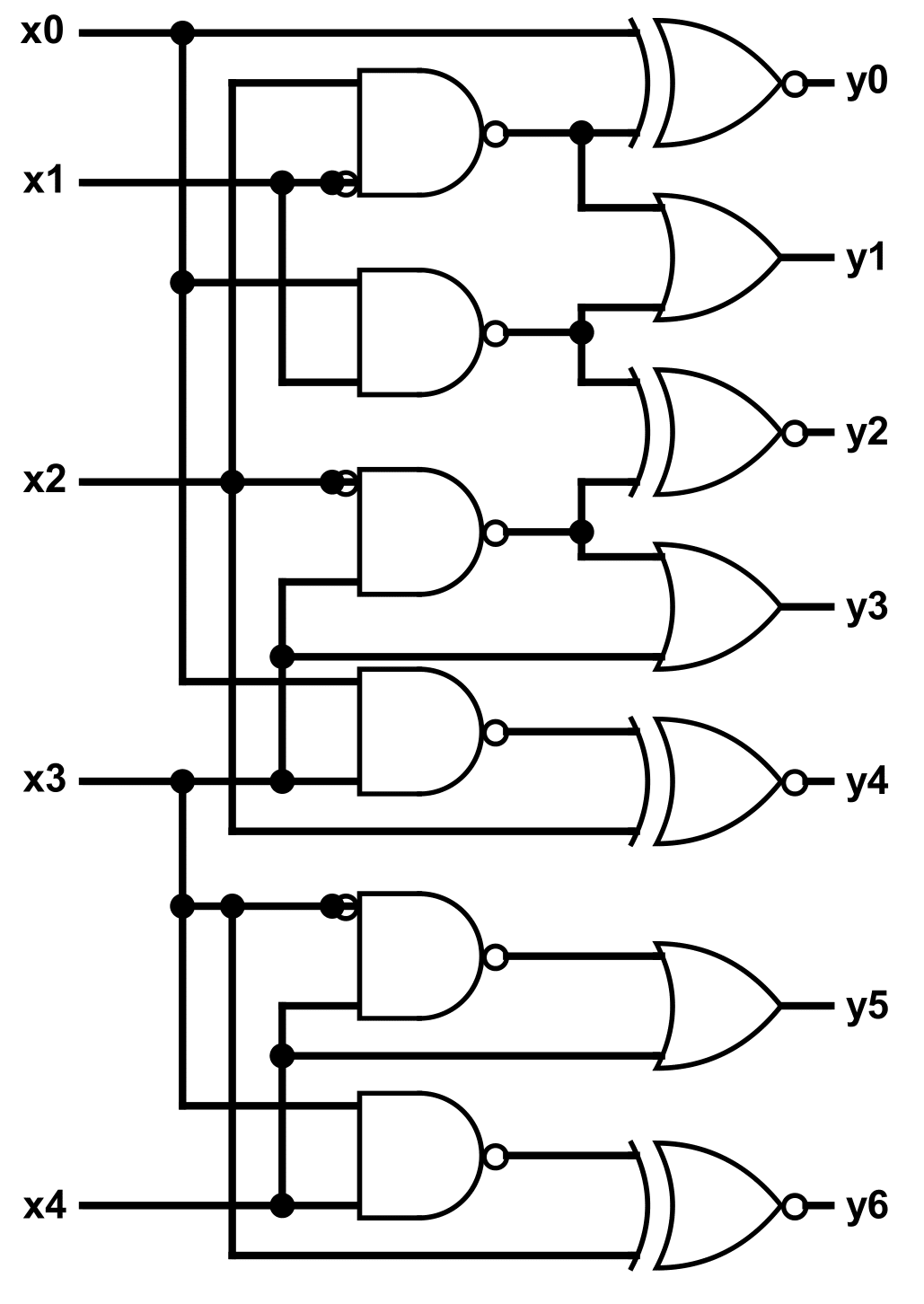
My solution looked like this:
The circuit consists of a combination of AND, OR, and NOT gates. We need to trace the input (x0, x1, x2, x3, x4) = (0, 1, 0, 1, 0) through the circuit to determine the outputs (y0, y1, y2, y3, y4, y5, y6).
Logic Gate Tracing
y0: x0 (0) is directly connected to y0. So, y0 = 0.
y1: x1 (1) is directly connected to y1. So, y1 = 1.
y2: x2 (0) is directly connected to y2. So, y2 = 0.
y3: x3 (1) is directly connected to y3. So, y3 = 1.
y4: x4 (0) is directly connected to y4. So, y4 = 0.
y5: x1 (1) and x3 (1) are inputs to a NAND gate.
The NAND gate output is the inverse of the AND gate output:
x1 AND x3 = 1 AND 1 = 1NOT (x1 AND x3) = NOT(1) = 0. So, the output of the NAND gate is 0.
This output (0) is connected to an inverter (NOT gate):
NOT(0) = 1Therefore, y5 = 1.
y6: x0 (0) and x4 (0) are inputs to an OR gate:
x0 OR x4 = 0 OR 0 = 0This output (0) is connected to an inverter (NOT gate):
NOT(0) = 1Therefore, y6 = 1.
Final Outputs
The final outputs are: (y0, y1, y2, y3, y4, y5, y6) = (0, 1, 0, 1, 0, 1, 1)
Flag Generation
The flag is formed by concatenating the outputs and surrounding them with ectf().
Flag: ectf(0101011)
Catch you later, 1337 and happy hacking!